Updated:
23-Mrz-07
DDDAC1543 MK2
Non-Oversampling, I2S-BUS,
Re-Clocking Modular DAC system with SPDIF and USB Input....
Introduction:
A quick view of the DDDAC 1543 MK2 family .....
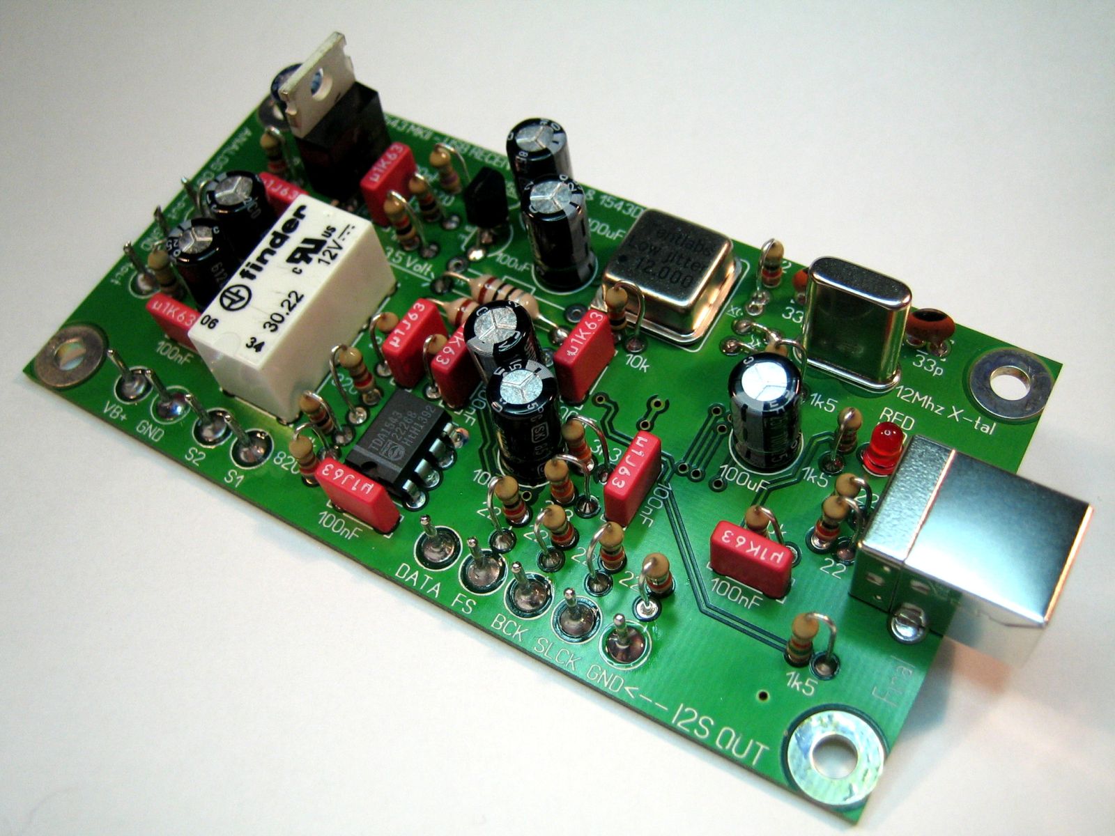
Left: USB
to I2S Converter & DAC with selectable analogue output: PCM2707 or TDA1543
NOS (replaced the "old" USB Converter)
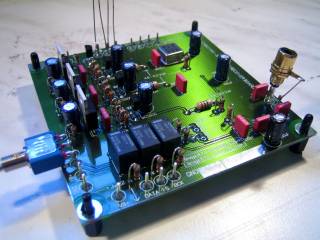
Middle: SPDIF Receiver with Tent XO Clock
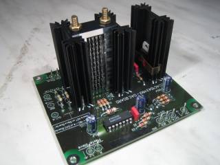
Right: DAC Module with tower construction and 12 x TDA1543
CLICK HERE for PDF high resolution document of the DDDAC1543 MK2 Family (version 5.0)
Click HERE for PDF high resolution document of the DDDAC USB Converter & DAC with selectable analogue output: PCM2707 or TDA1543 NOS
CLICK HERE to see how to connect the modules of the DDDAC1543 MK2 Family
Why did I worked out the MK 2 version ?
After almost 2 years after the introduction of the DDDAC1543, I have been receiving many many inputs from all very happy builders.... Never the less, I gathered a wealth of valuable inputs of people who improved the DAC or gave comments on the construction.... So what is new and improved in the DDDAC1543 MK2 ?????
Lots and lots of things !!!! Read here the whole list incorporated in the MK 2 version:
Professional double layer PCB with solder mask and component layout for easy construction, now lower threshold to start building....
Use of more easy to get parts, which keeps the price low !! ALL SMD PARTS are PRE-assembled by a professional contractor. NO hassle with trying to solder yourself SMD ....
More TDA chips in parallel. Improves sound quality
Modular set up with I2S Bus structure. Easy to create multiple DAC-chip construction in multiple of 12 TDA1543 chips .... No limit for die hard ultimate DIY :-))
Special Tent XO Clock with 2.8224 MHz frequency. No Clock dividing any more !! Direct clocking of the I2S Bus. Improves sound quality....
Separate SPDIF receiver with I2S bus input and output fixed with TENT Clock and asynchrone reclocking of I2S signals, improves flexibility....
Improved Low noise powers supply for each individual chip. Improves sound quality....
A solid heatsink and mechanical solution for the TDA1543-tower. Improves reliability & improves easy of building and no fan required .....
No bias control points anymore. Improves reliability
Battery checker integrated on SPDIF receiver and made simpler. Now a red LED will light up when 25% level of battery is reached
Not too bad for a second revision ............. ;-)
Introduction
and basics of the DAC:
I will not go into any discussion of the principles of the TDA1543 based non oversampling DAC, as I think this is described sufficiently in the normal DDDAC1543 section..... In stead, let me introduce the basics of this modular setup of what I like to call the DDDAC1543 MK2 family ......
In the block diagram below you see the basic Idea I had for the new version. Beginning with the inputs signals, From the USB port from the PC or SPDIF from the CD-Transport. Why USB ? The last year I have been reading more and more about DIY who used their PC as a music server and found out, that by bit-for bit ripping and playing directly from the harddisk to a USB DAC showed improvement over the SPDIF connection, where already many agree, that the basic standard it not fit for high end audio. The asynchrone reclocking basically proved that already..... At the Description page you can read more about the background and technical details of this USB to I2S converter as I like to call it.
The major improvement (at least I think) Is the concept of DAC modules with each their own power supply and I2S BUS buffered inputs. The current outputs are looped together in a master slave configuration, so basically unlimited DAC modules can be put together. I built for my self a version with 60 DAC chips in total (so 5 modules). This results in an stochastic improvement of 2,8 bits resolution. I believe it won't make much sense to go beyond this, as the amount of chips (AND Power consumption !!!) would grow ridiculously.....
To make things easy to set up, the PCB's are designed in such a way, every thing can be connected from PCB to PCB with short bridges.... see the description page please !
USB to I2S Converter
& DAC Receiver Layout
I mentioned the low noise power supplies per chip. Mostly done to isolate the power supplies of the individual IC's and their residual noise signals from each other. I have done some measurements (what else did you expect ?? ;-) to be seen at the results page....
Any way, this very simple basic power supply circuit is repeatedly setup over all the board, basic regulation, emitter follower and a 12dB/octave filter to isolate the chip. I use the 100uF capacitor to avoid a huge peak at the Fs and to keep the cut off frequency as low as possible in the range of 2kHz.
Basic Power supply filtering and decoupling
The battery checker was pretty complex and used hard to get IC's, so I "designed" (hard to call this a design, grinsss....) a simple version which is low cost and standard on the PCB.
It works as simple as it looks.... When the battery voltage is higher than roughly 11.4 Volt, the BC550C is conducting, shorting the RED LED. The green one will light of course as it is the power indicator. As soon as the battery drops far enough to have the BC550 stop conducting, the 2 LED are in series and the RED LED will indicate that the battery is aprox at 25% of its max charge. Feel free to use others colors by the way !!

Battery Checker
Making DIY
Life easy.....
You know me in the meantime, life should be
easy :-) So I wanted to have easy to use PCBs... Over the years a lot have
happened with PCB production and now I have been able to have PCB's produced
very professionally at a cost impossible for a few
years....
The layouts are below.... just click on them for high resolution versions !!!!
The "OLD" USB to I2S Converter & DAC Receiver Layout (Size 50 x 100 mm)
And here the NEW One:

SPDIF to I2S Converter & Receiver Layout (Size 100 x 100 mm)

DAC Module.... (Size 90 x 100 mm)
Details
how to set up a system
If you click below on the image you will get a
high resolution image which shows how to connect
the different modules.....

added Jan 9th:
Power
Supply Considerations...
I am getting a lot of questions about the
batteries or power supplies to be used. So let me try to "answer" your
questions upfront ---->
What Battery and Charger to use:
Use a 12 Volt (Gel) lead-acid battery from the "maintenance" free sort. Good examples are to be found from Panasonic, like the UP-RW or LCR series. But also cheaper imitates like the Korean brand Long will work fine (I am using those by the way...)
In terms of the capacity, you could use the following rule of thumb:
[Capacity of Battery in Ah] = [Requested time the DAC will run in hours] * [number of DAC modules]
In practice,
this will let the DAC operate roughly till the point where the battery checker
starts indicating the 25% level...... So this rule is at the safe side so to
speak :-))
Example: you want you DAC to run at least 5 hours in one run (like one evening
listening...) and you have 2 modules. Than take a 10Ah Battery....
For the
charger, there are only two specifications which are important:
1. The charger should be automatic, which means, that it
should be allowed to keep the charger attached to the battery, even if the
battery is already at 100% charge
2. The charge current should be approximately
10 to 15 times less that the capacity in Ah. Example: you use a 15Ah Battery,
the charger should have a nominal charge current
of 1A to 1,5A...
These can be found in almost every electronics shop !!!
Mains Power supply:
If you do not want to use batteries (may be the DAC is always on ?) you can take a normal 12Volt power supply. If you design one yourself, you can make it 11 Volt to safe some heat dissipation on the DAC Modules....
Any DC power supply will do but there are a few things to consider:
1.
Cheap net adapters sound somewhat harsh and
trouble the whole image.... rather not use these other than in between
or for testing may be ...
2. Use some "overkill" to make sure the power supply
is working at easy. I would suggest to do 1A DC capacity per DAC Module !
3. I heard some very good
results when using low noise unregulated power supply designs..... Using quality
components.
I give here a
UNTESTED example of how such a power supply could look like..... For you to try
on your own "risk"
Please look at this as a design idea to guide you to do your own
"design"
The values are relatively uncritical and can be used as a guideline again.... I
made this with a 12 DAC version in mind ....
In practice you should be able to fine tune this circuit with the value of the
zener diode your self ....
POWER SUPPLY IDEA:

For higher power use, the above might prove to be tricky if you have little electronic design experience. I would like to show below a somewhat more basic version of a power supply which will easily go up to 5 Ampere (enough for the DAC-60 ....) This has no need for fine tuning and will just work fine (also for 1 DAC)
POWER SUPPLY IDEA for higher currents:

Read all technical construction details and results at the next pages
If you are interested to built a DDDAC 1543 MK2 system for your own, see my sales page and the KIT Story.....
Happy Listening and Building !!!!
Doede Douma
IMPORTANT: The information provided on this page is intended as guide for DIY activities and therefore free to copy and or publish. If any one wishes to use any of the information from my WEB site, please make sure to refer and footnote to my URL Link as source! Doede Douma