Basic MU Stage
Updated:
20-Aug-01
Doede's Other Audio
Projects...
This will be partial technical, but for the less technical reader I will try to give clear conclusions. You will have noticed, that most Tube Stages I am using are based on the MU principle. What makes this MU stage so great? Let me try to explain:
Triodes are typical Voltage amplifiers with a relatively high internal resistance called Plate resistance. ( Rp) For normal Triodes round 10kOhm The ability to change the current through the tube by applying a voltage on the grid is called the transconductance. ( S or gm). Normally this is round 2 mA/V. So if you apply 1 volt at the grid the current through the tube will change with 2mA. If there is no load on the tube. This current will produce 2mA * 10kOhm = 20 Volt at the Anode. So we amplified the 1 Volt 20 times. This is called the MU from the tube. This MU is quite constant. So MU = Rp*S. Well if you load the tube the voltage and thus the gain will be lower. Or to get the same Voltage at the output we need more volt at the grid. Example: we load with another 10kOhm, Vout is now 10Volt (2mA*5kOhm). For the old 20 Volt we need to apply 2 Volt at the grid ! so the Gain is now 10, we can say: (Gain = MU * Rload / (Rload+Rp))
If you would look in the Tubes plate curves, you would also see that by loading the tube, the tube becomes less linear… THIS IS ALL WHAT WE DO NOT WANT !!!!
Still there? OK, the best results would be there if the tube can swing freely and there is no current change, just voltage gain. IDEAL SITUATION !! So lets put a load of lets say 1 Mohm to the tube (1:100 seems quite unloaded to me…) . Yes it works, but if the idle current or bias current is aprox 4 mA (realistic value) the Power supply must be 4000 Volt, mhhhhhhhh, not very practical. Is there a fix where we can have low power supply voltage and low loading of the triode? YES: it is the MU stage !!!
Basic MU Stage
Just watch what happens: the voltage at the grid will be amplified at the anode of the triode. Assume the voltage goes up here with 20 Volt. This voltage is lead to the grid of the upper Tube, a Penthode which is operating as a Source follower. Interesting, the increase of 20 Volt is now supplied to the top of the Loading resistor of the Triode… Well if the voltage at BOTH ends goes up with 20 Volt, the resistor does not see any difference from before, so the current stays the same. This means that the load of the tube is infinite !!! If the output needs any current, no problem the Penthode can deliver this without changing the voltage at the cathode…. Till the may idle current (10 mA or so). The Gain is now equal to MU, so that’s why the name is MU stage….
Is it that simple? Almost…. It comes very close. If the transconductance. from the upper tube is very low, than the Ugk will change with the current change through the load from the MU stage itself and this gives a little change at the top of the resistor, so it is not really infinite. How much is it than? I will not do the calculation for you, but it is Rload = Ra* MUpenthode. That is why a triode is less useful on top. With a MU of 20 the Tube load with a Ra of 10kOhm is now aprox 200k. The MU of a Penthode can be easily 1000 !!! (S * Rp) so the tube load will be 10Mohn. In practice you won’t reach this complete, but if it is more than a Mohm, it looks fine to me. Just finalizing: Do we need the grid2 resistor from the Penthode and the capacitor? Yes we do. The grid2 voltage defines the linearity of the Penthode and the MU factor and it needs to be constant. The C keeps for audio frequencies the voltage between the cathode and the grid2 constant. Unfortunately these two parts are loading the MU stage. Well, no problem you say…. Make the Rgrid2 very large, good try, but the you need current in the second grid, otherwise the Penthode won’t work and will most likely give more distortion… But it is not such a big problem. The Penthode is a current amplifier from nature, so it can deliver the load without problem. Is there an optimum? Yes there is, and this is what I have been measuring. Why is there an extra load from the output to ground? Simply because the Penthode works fine at aprox 10-15 mA. The triode mostly at 4-6 mA, so we deviate the rest of the current. This has 2 advantages. The max current which we can supply to the next stage (think of nasty Miller C’s and slew rate…) is higher now and the BIAS point is self regulating. You almost can’t do everything wrong. The MU always find a BIAS somewhere in the middle to 2/3 of the Supply Voltage……. Easy ehhh?
Lots of theory, but I wanted to know more, so I have set up a test bank with a 76 triode and the ability to test several Penthodes.
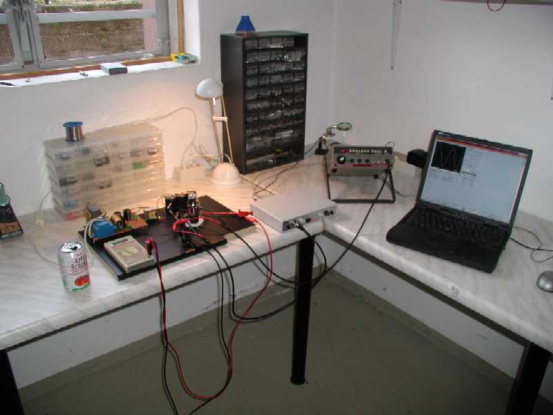
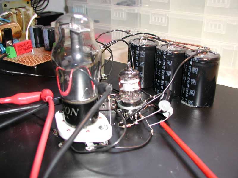
My MU LAB .........
I spent many many hours downstairs but was very happy with the results…. In the PDF doc’s you can find a XLS sheet with all the results and pictures of the Harmonic distortion profiles (mutest.xls, the FFT pictures mutest.zip) . BEWARE: techies only….. for the less technical reader who may be want to experiment with the MU stage him or her self, I list my conclusions below:
What did I basically tested?
What have I measured?
What are the results / conclusions? (random order)
This is all the technical stuff. Next comes the listening. I have compared so far the 6688 with the D3A. The last one runs with Rg2 of 20kOhm (in my 300B) and is my preference now. The 6688 is also very beautiful, but just a little bit less….
Next Step: the DMU ! I went one step further and try to find a solution, where the Rg2 was not necessary. I found the solution (and later found out it has been published already a few before in Glass Audio, hahaha !!) by putting to ECC88/6DJ8 (I used PC189, stock on hand…) in cascade kind of MU. This means that the 2 MU’s of the triodes can be multiplied, resulting in Penthode kind of MU’s, but with no grid 2 !!! as the tubes can run at lower current, you do not need the extra load to ground. Sounds good don’t it? I have built this one in the LAB as well and the results were very promising:
The Double MU
Well, as soon as I have listened in to the Penthode MU’s I will build this one on the 300B amps and report
************ HERE **************
to be cont’d
IMPORTANT: The information provided on this page is intended as guide for DIY activities and therefore free to copy and or publish. If any one wishes to use any of the information from my WEB site, please make sure to refer and footnote to my URL Link as source! Doede Douma