Updated:
10-Jan-06
DDDAC1543, a Non Oversampling, Re-Clocking DAC
Introduction
This time, start
with a view images before we start with boring text :-)
Or jump immediately to the introduction text
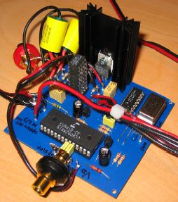
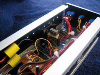
The prototype
DDDAC1543 on the newly designed PCB. At the right the DAC Tower with special cooling !!!!
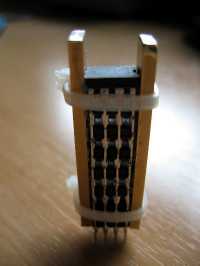
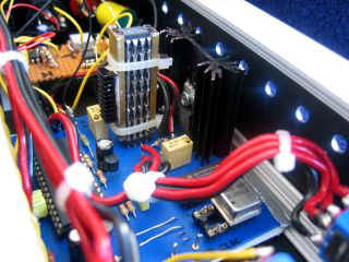
I had several questions on how the DAC tower was made, so
click here for some detail
Image of the PCB, complete with Bonus PCB. Read further at the bottom of the page !!
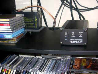
Below the finishing of the DDDAC1543 in a serious piece of Audio Equipment.....
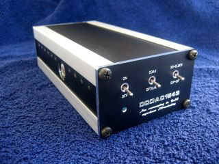
At the top, the
final Enclosure, which I was able to design exactly to my wishes and through a special
design tool and WEB-order procedure from a German company Schaefer...
You can download this
"CAD" software and get all info here
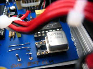
A look in the inner world of the DDDAC1543: At the left the special DAC TOWER and at the right the Tent XO Clock
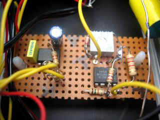
MMMHHHHH, another
test PCB??? To be honest, yes, but have nothing to do with the DAC itself. This is just
another Batter Checker !!! I can't get enough of them you probably noticed..... This one
makes the "on"-LED blink as soon as the Battery voltage drops below 11.4 Volt
(adjustable)
Click here for the very simple circuit !
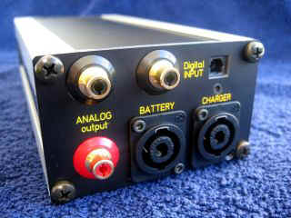
at the right the back-panel with connections for the Battery, charger and audio equipment
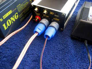
DDDAC1543 in full working order.........
CLICK HERE for PDF high resolution Circuit of the DDDAC1543 (updated version 2.2 !!)
Introduction
and basics of the DAC:
This very interesting project started
with a visit to audio friend Dick beginning this year. After all the normal things
audiophile friends go through when they meet, he grinned and came with the jack in the
box..... let me listen to a new DAC he built and beside some little comments (which are
already fixed by the way) I was VERY much impressed by the dynamics and extreme pin point
!! Then he revealed what this was, a very simple non oversampling DAC with a TDA1543 and
only a R(I/V) resistor as output. No transformers needed to get an output of aprox 2Volt
RMS out. Needless to say, no OPAMPS needed as well :-) Input was done with a CS8412
S/P-DIF receiver. Nothing new I found out later, as there seems to be a whole community on
the WEB building this nice little and cheap DAC.... I decided to build a prototype with
enhancements (Otherwise there is no need for this site, eh? :-) to see if the small
backdrops from the DAC (bit fatigue some times and less low level detail and spatial room
compared to some other good DAC) could be improved. I had basically 2 ideas:
To make a long story short, this proved to be the solution. The 2 extra tweaks have been upgrading the 1543 DAC dramatically. Also by measuring distortion spectra, I was able to determine that the DC biasing is of extreme importance ( !! ) ..... Listening test between the original DAC from Dick and also from "Email" friends have proven this !! I will come back to this on the "RESULTS" page
Of course I have designed a PCB, so a professional construction, flexible use and bias adjustment will be possible...
NON-oversampling....
Although you can find literary
hundreds (thousands?) of articles on this subject, let me do a short summary of what I
understand is the whole thing (and no magic) about it....... In the early days of CD
technology, there was no such thing as oversampling and huge so called brick wall filters
were used to cut off the spectrum above 22.1 kHz. Of course this is not easy if you want
have a low pass till 20kHz.... so as soon as technology improved we saw 2,4,8,16 times
oversampling, making the effective sampling rate much higher and therefore the filtering
of the mirror spectrum above 1/2 Fs is much easier. Compare this with the DDDAC2000 where
filtering is done trough means of the transformer and the first tube stage. Why is this
bad then ???? Well lets make a side step. When I first heard SACD I was impressed by the
pinpoint, spatial sound and dynamics. Read articles about this and you will bump into
articles on FIR filters....... What are FIR filters? Very simple, they are digital
filters, making use of the time domain to create a frequency domain response. Not very
clear eh? I agree, but what the basic thing is, that FIR filters introduce PRE-RINGING and
POST ringing Like this:
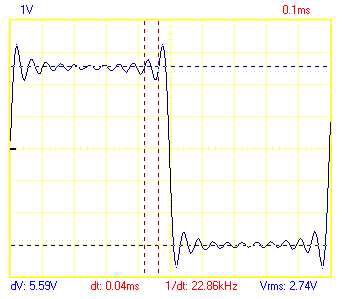
SACD for reasons of the much higher FS (2Mhz aprox) has MUCH lesser pre-post-ringing. I cannot show a picture, but if you click here, you will have an extract of a document on DSD signals, where a nice comparison is made on the response of a single impulse. It is self explanatory ( I Hope, otherwise email me...) Now a picture how a square wave looks like from the DDDAC1543 (straight R(I/V) output at full 16 bit scale, no filtering):
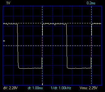
So the idea behind all this is, that if the transients are more precise in time and not smeared around, the stereo image will be more in focus and more pin point.
I know it is arbitrary, but are those not exactly the testimonies from listening tests to NON Oversampling and DSD ????????? Why are commercial manufactures not doing this then you ask ???? Good question: My best guess is it is done, because the Non Oversampling DACs without a filter measure terribly !!!!! No good marketing, haha !! But we, DIY audiophiles don't care, don't we?
Filtering of the
"beyond 1/2 Fs" portion
OK, nicely said, but was there
not something about the very difficult analogue filter and won't this screw everything we
just gained???? YES !! and the solution is so simple........ just omit the filter. But
then we hear square waves, does this not introduce huge distortion ??? yes, but only at the
3rd harmonic of the base square wave frequency, which happens to be 44.1 kHz. Our audio
chain and finally our ears will do all the filtering we need. Hard to believe, but it
really works !!!! It is truly amazing if you look at the scoop and later you cannot hear
any difference with a pure tone!!! If you don't believe, just try it and convince your
self. I admit, it sounds weird, but this is really the case...... So no need for lots of
techy stuff here :-)
Lets move on to the real enhancements ------------->
Re-Clocking
Again, thousands of
articles on S/P DIFF receivers and their inability to recreate real low-jitter clock
signals. I think we all agree in the mean time that a low-jitter clock makes the sound
more open, spatial and gives a lot of rest in the sound stage. Also all kind of tricks for
the VCO (Voltage Controlled Oscillator) are to be found on the WEB. They are all
absolutely valid, but still it is a "dirty fix" to recover the clock from the
messy S/P-DIF signal. So what is the solution on hand? Indeed, good old re-clocking. Ok,
ok, if you have a CD-Drive with direct I2S signals out, you win.... but this is not a very
flexible solution. For home brew DIY just fine and I must admit I play with the thought to
build my own CD-DRIVE supporting this ultimate (yes !) solution. Back to re-clocking, the
idea is simple, you let the signal come in with what ever jitter is on it and you re-clock
(re-sample is actually the better word) with a new clock. There is no REAL need for the
same frequency by the way, but later more about this..... If now this clock is LOW-JITTER,
we achieved our goal as the DAC is clocked by this signal as well !! I already had very
positive experience with this phenomenon with the DDDAC2000. You can still read about this
on the other pages......
Back to the frequency. In the DDDAC I used 24Mhz, which sounded fine, as the signal was afterwards 8 times upsampled and digitally filtered. NOT with the DDDAC1543 !!! Here we have NO filtering at all, no digital, no analogue. So what happens if the clock is kind of asynchronous?? You get very bad mixing, inter modulation distortions so to speak. It is so bad, you hear it when a soprano sings a continuous tone. Sound like a square wave....... OOOPSSSS, what now? NO problem, Guido Tent is selling his XO1 clocks, which are low jitter oscillators with exact 256Fs frequency (11.2896MHz). The later XO2 and XO3 versions can be used as well, but as I use a Battery Power supply, I see no use in the extra electronics around the oscillator which is merely a super low noise power supply for the XO1 clock........ If you would run the DDDAC1543 from the mains, a XO2 or XO3 clock would be better I guess
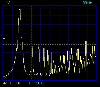
Well, what about this jitter, is it really that bad? YES !!! I measured it and this is the spectrum from the derived bit-clock, which I think is the hart of all. This clock defines WHEN the next sample is led to our ears. If this is not done in a very constant pace (jitter...) we get all the problems, we collectively believe is the result of jittering clocks.
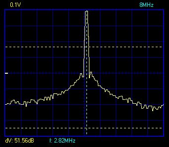
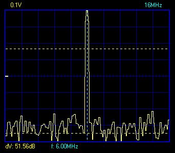
DO I NEED TO SAY MORE ???
So I choose to use the re-clocking and for the dis-believers, I designed the PCB in such a way (see circuit description) that you can easily switch between the 2 clocks. A built in A-B listening test comparison !!!! Check the "Results" for listening tests ...
Paralleling DAC chips
OK, last but not least,
parallel DAC's...... Why this? Actually the TDA1543 is not know for its great linearity
and great performance. And this is already a huge understatement, haha !! Why use the 1543
then? Simply because it runs on almost 9 Volts and has a current output. This enables us
to make directly 2 Volt Output (CD Standard) without any further tricks than connecting a
resistor to the output........ Back to the 1543 quality, so it is lousy? yes it is, but
thanks to statistical laws we have a way out !! If you run (ANY !!) process many times,
after each other or in parallel does not matter, the uncertainty or errors in the output
of the process will improve with the function of SQRT(n) where "n" stands for
the number of events. This trick can be used for example to get very precise resistors or
capacitors by paralleling them. Thanks to the current source output we can easily do the
same for the TDA1543.......
Is there an optimum? I am sure there is, but I was not so crazy to try all possible variations of "n".... I tried in a prototype 3 DAC's in parallel and this was a major improvement. The low level detail, known from high bit systems was really improved. Listening to the 8 DAC version, it comes very close to SACD.... not bad I think (again an understatement... :-) So how many is realistic? well for each doubling of improvement, which equals 1 bit extra of linearity we need to multiply "n" with 4 !! so with 8 I get one and a half bit extra, which actually is already very good. If I want now 4 bits better performance I need to put 4x4x4x4=256 DAC's in parallel. This will consume 12A supply current and dissipates 100Watt. Feel free to do so, but it seems a bit unpractical to me, not even mentioned the circuitry needed to drive the 256 TTL inputs !!! Why did I mention 4 bits? Well, according to the datasheet, the 1543 is aprox 12-13 bits effective. A PCM63 by the way is also not much better then approximately 15 bits effectively. All the rest is marketing :-) So the choice for 8 is purely based on a combination of maximizing "n" and keeping things within reason technically.........
There is also an additional EXTRA bonus by doing this: by paralleling the DAC's we have to decrease the R(I/V) resistor as the current increases. So the Output Impedance is also reduced by "n". This helps a great deal driving the interlink to the pre amplifier of directly to the end stages if you do so...
Furthermore, the DAC pinning makes is possible to just piggy back them..... this resulted in the "cool tower" you see in the pictures.........
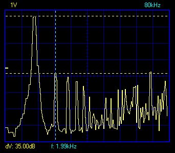
Can you actually measure the improvement? Oh yes, no problem ! below, from left to right the 2 results of 1 DAC and 3 DAC, which is almost 1 bit improvement. Both Measurement at optimum. You might think, the difference is low, but this is exactly (3dB is 0,8 bit) what helps the low level detail to play at less distortion !!
Happy Listening and Building !!!!
Doede Douma
IMPORTANT: The information provided on this page is intended as guide for DIY activities and therefore free to copy and or publish. If any one wishes to use any of the information from my WEB site, please make sure to refer and footnote to my URL Link as source! Doede Douma