Updated:
11-Jan-03 17:59
Doede's Audio Tweaks...
Updated Jan 11: click here to go straight down to the final solution !!
Introduction (March 16th)Description
So, for the first try, I will make my life simple and use the I/V converter with the first OPAMP. After this converter, the double balanced signal is single balanced and this can be made single ended with the Sowter Transformer ! Followed by a simple 6dB filter at 100kHz, this must be sufficient, I thought. Just have a look below where I tap of the signal for the transformer. PLEASE NOTE, that the output signal is completely FLOATING from the CD-Player, so take care for ground loops through the Power cables. They can induce HUMMM. I do not use the power grounding, so my signal is as quiet as , uhhh, as what? Well, quiet! I hear nothing, so that must do......s
Details on how to do this:
At the left, an overview. The RC-filter is wrapped in the Shrink Tube. At the right: Space
enough, no problem !!
How does it sound????????
Big big thing ??? No, another class? no, Worth it? Ohhhh YES !!!! This little tweaks goes into your subconscious. After listening a while you can blindly recognize this. If you switch back (just plugging the cinch cable in the other connector) you immediately hear the little harshness coming back and you know that you want to go back to the new situation and stay there.
Ready ????
Are we finished now with the 777 Tweaking ??? No, I still want to by pass the
"last" OPAMP as well (the I/V one) and make it totally passive. But I still need
to think on how to do this best..........
Update March 17th
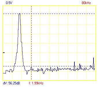
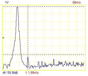
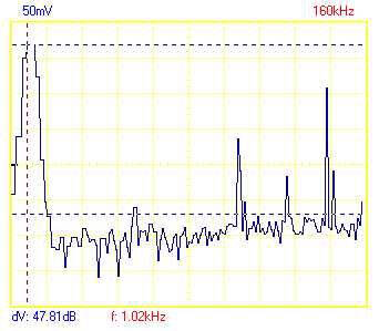
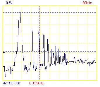
Left: FFT picture from a 1kHz Sine wave taken from the standard Sony output, Right the TX output. Need to say more ??? hahaha!
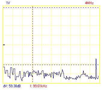
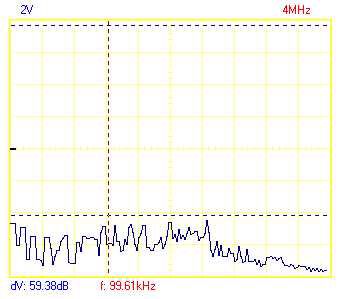
The same, but no the FFT window goes to max 4Mhz, In the Sony Output at the left , there is still a H.F. component !! In the TX Output at the right, quiet as..........
Ok, here the Sony output wins..... clearly the TX output does not go that low in frequency. Actually 25Hz -3dB. By the way, the terrible (pre) ringing is typical for the CD filter. I only had a test CD, no SACD. on SACD you will not find ringing like this. Mhhh need a SACD test disk........
Conclusion ??And now the serious stuff: the Final Solution without OPAMPS (March 17th)
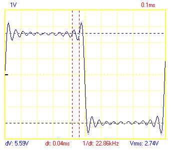
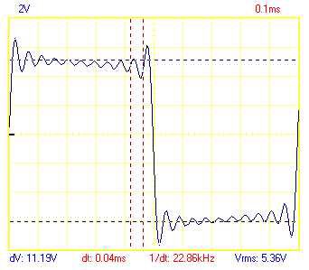
What I did, is isolating one of the 4 current outputs from the DAC, by very carefully desoldering one of the 47 SMD resistors...... pfffffff....... Now I loaded the output with a 2 kOhm trimmer and turned around a bit whilst playing the 1kHz Sinewave tone.
Top: This is where there is still no distortion. R = 600 Ohm Output is
450mV RMS
Bottom: OK, here we see total mess from the curentsource, R=2kOhm Output is 610mV RMS
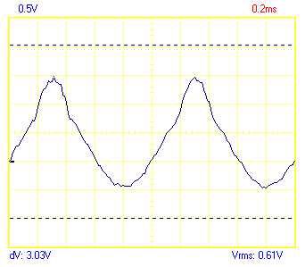
What do we learn? In theory we can load the positive and negative Iout from the PCM1738 with both a 600 Ohm resistor and get 900mV RMS out of it. This could be done, BUT I have a few reasons NOT to do so and use this measurement only as an indication of where the safety limits are:
The internal resistance from the Curentsource (I will spare you the calculations I made based on triple references) is approximately 700 Ohm. There is no hard rule, but you want to load a curentsource with a far lower impedance than its internal !! 600 is FAR too high. ZERO Ohm would be optimum, but than there is no Output-voltage left, so what now? let's go on first and see later
I definitively do NOT want to demolish all of the audio boards in the 777. Actually I want the normal Sony Output to be active. Not only for stereo, but also to sustain the 5.1 multichannel output.
I want to be able to switch between the old and new situation. This can only be done by relays, too many lines need to be connected (24 Iouts remember?)
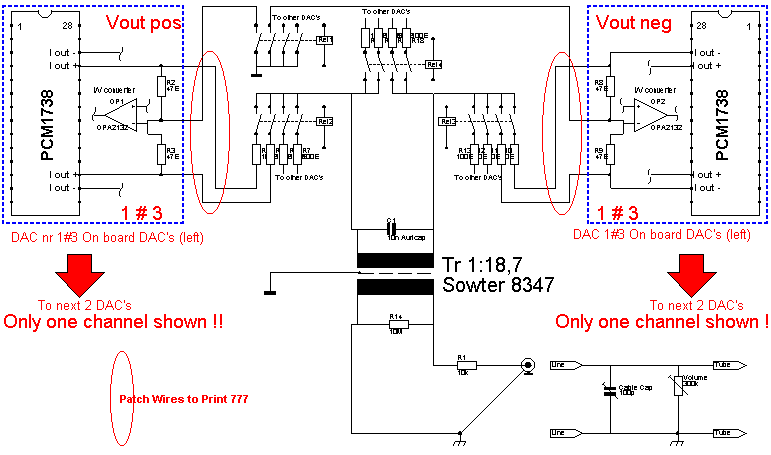
I have very good experiences with the Sowter TX 8347, specially made for DAC applications, better linearity and bandwidth. the ratio here is 1:18.7 (I have always found this a very strange ratio.........but who cares?) With this ratio, we only need aprox 100mV or so.
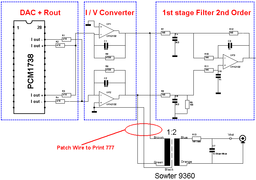
At this point I had my brainwave ! Just have a look at the circuit below and see what I have in mind....
We actually use the 47 Ohm resistors which are on the audioboards already and are very easy to access as "patch-point"
At the DAC side of the 47 Ohm resistor the Output voltage from the DAC is available IF we ground the other side. You could argue that the minus input from the OPAMP is already ground level..... Yes it is, but it is a virtual ground, so the OPAMP is STILL in the signal path, No, no, no, by the relays we just connect this point to REAL ground. The OPAMP has no problem with that, and by doing so, we more or less ISOLATE the whole OPAMP stage from the DAC, without desoldering or cutting PCB routes.........
Through a whole series (24) of 100 Ohm resistors we more or less "add" the 6 positive outputs and the 6 negative outputs per channel. Why 100 Ohm ?? just a round value, could have been 47 or 150 as well. Just a hard wire could also work, but I want to make sure, that the little offset differences in DC at the Current outputs are NOT leading to too high offset currents. 100 Ohm seems a good value to me, so let it be.
The positive and negative are now loaded by the TX which makes it single ended and is removing all common mode error signals and filtering the high frequencies as well.
The source Output will be 150mV eff. This is all very nicely within a wide range of the supply rails and with the 1:18.7 this will bring the output to 2,8Volt RMS. More than enough for my Line amp.
This is what I will built soon..... a lot of relays, so need to check if there is enough current available in the 777. Otherwise I have to build in an extra power supply.
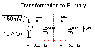
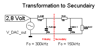
What the heck is this here? Transformations??? Well it is to show the output circuit from 2 points of reference:
From the DAC perspective, to see if the load is not too high. As you see it is not and the filtering is done smoothly and outside the audio band
Perspective from the input circuit from the Line amp. Do we have enough Voltage ?? Do we have a low impedance source to drive the line amp ??
The answers on the questions are, that the load for the DAC is absolutely ok and that the source impedance for MY LINE AMP is fine. But be aware !!! If you want to drive a 20kOhm Potentiometer in an integrated amplifier or so, FORGET it. You will need to put an extra (tube) stage in between !!!! So I tweaked the whole thing for my personal audio. This is a not a 100% overall solution, working with every thinkable amp in the world !!!
If you want to know if it is appropriate for you(r amplifier)? As a rule of Thumb, do not load the TX output below 100kOhm and do not use interlinks with a capacitance of more than 200pF. Well, that isn't quite impossible, eh? I have ordered the Relays, so I can start building soon. Than I will be able to report on the final audible impact......
Update March 19th
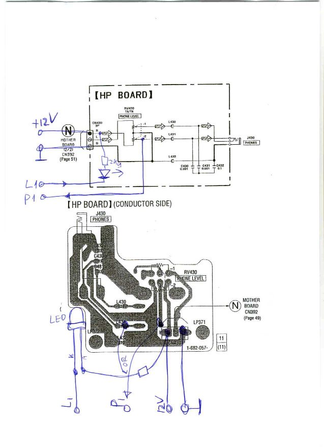
An interesting solution to enable Frontpanel switching between the Sony output (handy for A-B comparison AND to play 5.1 mode...) and the TX mode is the little circuit at the top right. I use the existing Volume Potentiometer for the Headphones , which I do not use anyway, as a variable voltage divider. The voltage from the tap is lead to a comparator with hysteresis. If the pot is turned to one end, the comparator will switch a relays, which on its turn switch all the other relays and actually putting the whole TX-Output in place. Actually the original output at the back is switched as well between Sony and TX...... So no need to switch cables over and over again !!! The indication which one actually is playing (I do not want to have blind testing all the time...hahaha) is a LED which I will stick into the 6.3 mm Jack connector for the headphone. So no drilling, no nothing and the 777 stays intact. Weird idea? may be yes, but it complies exactly with what I wanted..........
To be cont'd !!!!
Finalization
(January 10th)
I finally find some time to actually
start building this tweak, which is quite some work to be honest. The principle is
extremely simple: Through a bunch of relays the Current Output from all 6 PCM1738 DAC's
are bundled into 4 signals, Left / Right and for both POS and MIN. This combined signal
(therefore all the resistors) is being up lifted by the Sowter Transformer, Case ready.
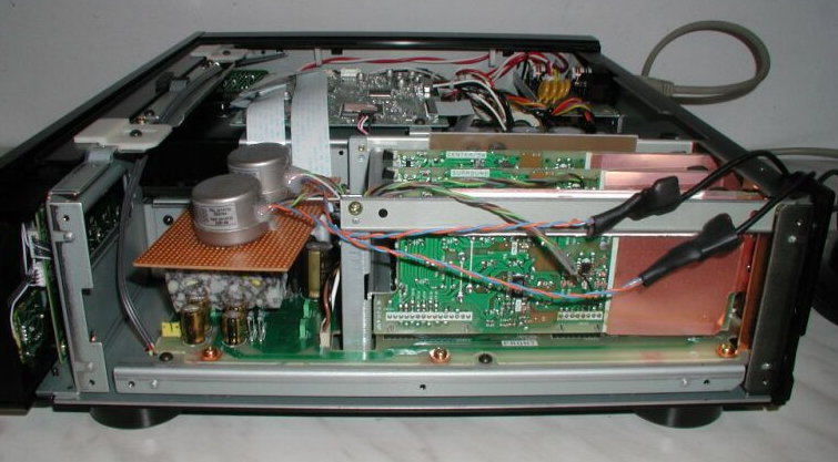
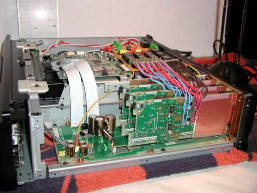
The most precise work is the wiring in the Sony 777, not to mention the disassembly of the
chassis. I will limit my self now to the image details of the construction and (of course)
the sound impression.......

Actually Built Version 2.3 shows here: Click the circuit for double Resolution !!!!
Or click here to get the full version 2.3 PDF document
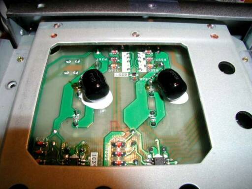
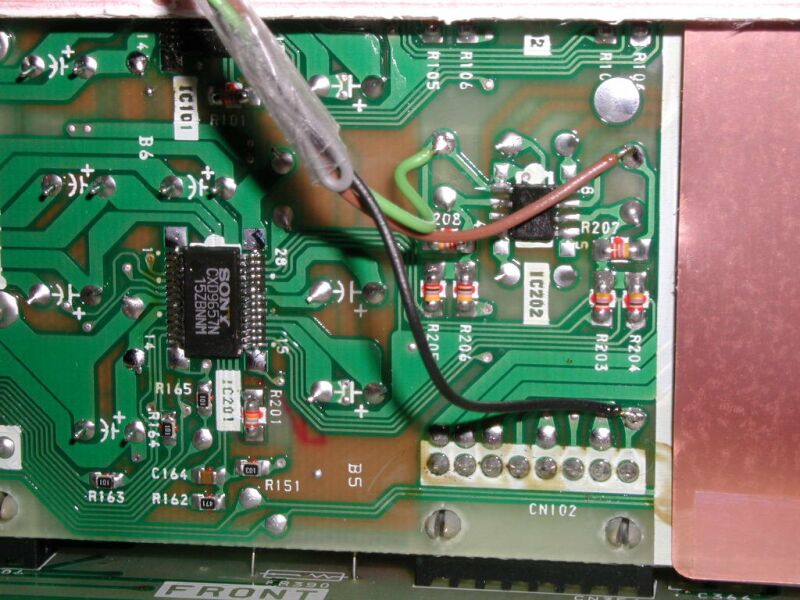
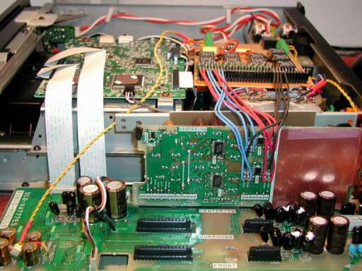
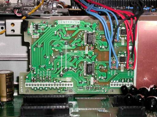
The 777 Sound Motherboard,
location very close to the stereo output cinch
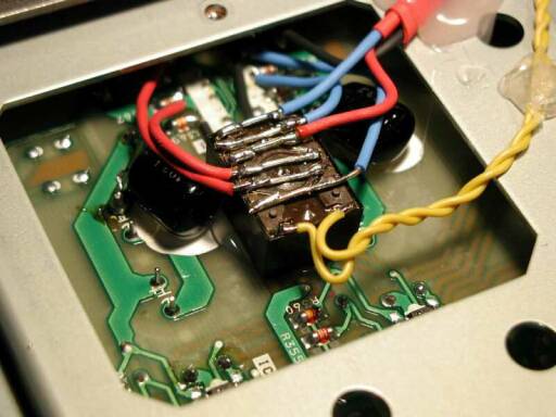
The 777 Sound Motherboard, but
now with the relay , switching the output terminal between Factory output (OPAMPS) and the
transformer output. The yellow wires are the wires coming from the Comparator circuit
which is driven by the headphone volume control....
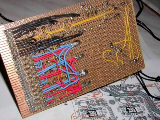
This is how the PCB is hard wired, All
Silver Wire !!!
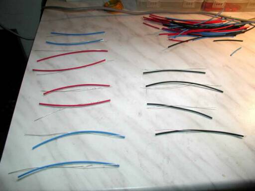
Preparations for the Silver Wiring of
the DAC boards to the PCB...
At the front you can clearly see that
the DAC boards # 2 and #3 are taken of the motherboard. This gives room to solder the
wires...
Detail of where the signals are being
"tapped" and lead to the relays PCB... Very careful soldering here !!! Before
you know the small SMD resistors fall of !! Quite some work to get them back.... Speaking
from experience, ahem....
OK, at the end, when all 3 DAC boards
are wired, this is the result !
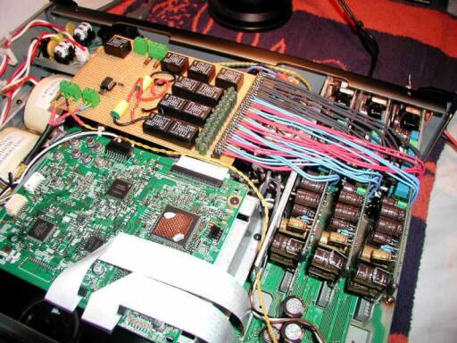
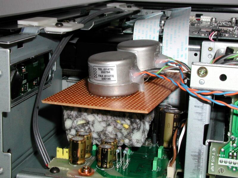
The same, but from a different
perspective... The Sowter Transformers can still be recognized. They are glued at the
chassis, right under the signal wires...
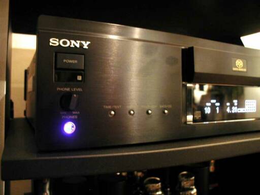
This is how it works with the
headphone: When the Phone Level Control is turned clockwise, the LM311 comparator will
change state and drive the relays to take the Transformer "position" and the
signal LED will shine through the Phones jacket (just glued the LED behind the 6.3mm
jack) CLICK here for details on how to make the
connections..... When turned the other way, the relays will fall off and the
original factory circuit is complete back in place without any interference (well, one
relays contact than....)
The burning Question:
How does it SOUND ????
When I bought the Sony 777, I
was wondering how OPAMPS could sound so good. Actually they really do in the 777....
So I was very curious if the transformer tweak could do any good here !! The day the tweak
was ready I plugged in and was a bit disappointed..... there was hardly any
difference !!! All this work for nothing and are OPAMPS really ok than ??? I stopped
listening and let the 777 play day and night in the transformer position. After a
few weeks this really made a difference now !!! It seems that the MU metal in the Sowter
transformers needs quite some time to get burned in. Good to know for the next
time...
As know by now (yes ??) the transformer output can be selected by the former headphone volume control, so I can try it over and over again, real A-B comparison. Compared to the transformers, the OPAMPS sound harsher. Remind: RELATIVE !! OPAMPS can sound much much sharper !!! It is a very relative world we live in.... The 777 with the opamp output is indeed very good, actually I have not heard of any thing better in this price class (and above...) so far. Than you turn the knob and hear how good it becomes with a transformer output. The gain is actually in the pinpoint definition, depth/width of the soundstage and the clarity of the high frequencies, very very smooth, very analogue..... This was definitively worth it !!! For a short while I thought OPAMPS could do the job, but now I know better, they are a limiting factor at the end after all.... In the meantime I do not need the signal LED, Sometimes, when I sit down to listen some music and up goes the eyebrow, what is wrong here??? MMHHHH, missing something, check the LED and yes..... need some turn clockwise.....
Happy Listening and Building !!!!
Doede Douma
IMPORTANT: The information provided on this page is intended as guide for DIY activities and therefore free to copy and or publish. If any one wishes to use any of the information from my WEB site, please make sure to refer and footnote to my URL Link as source! Doede Douma